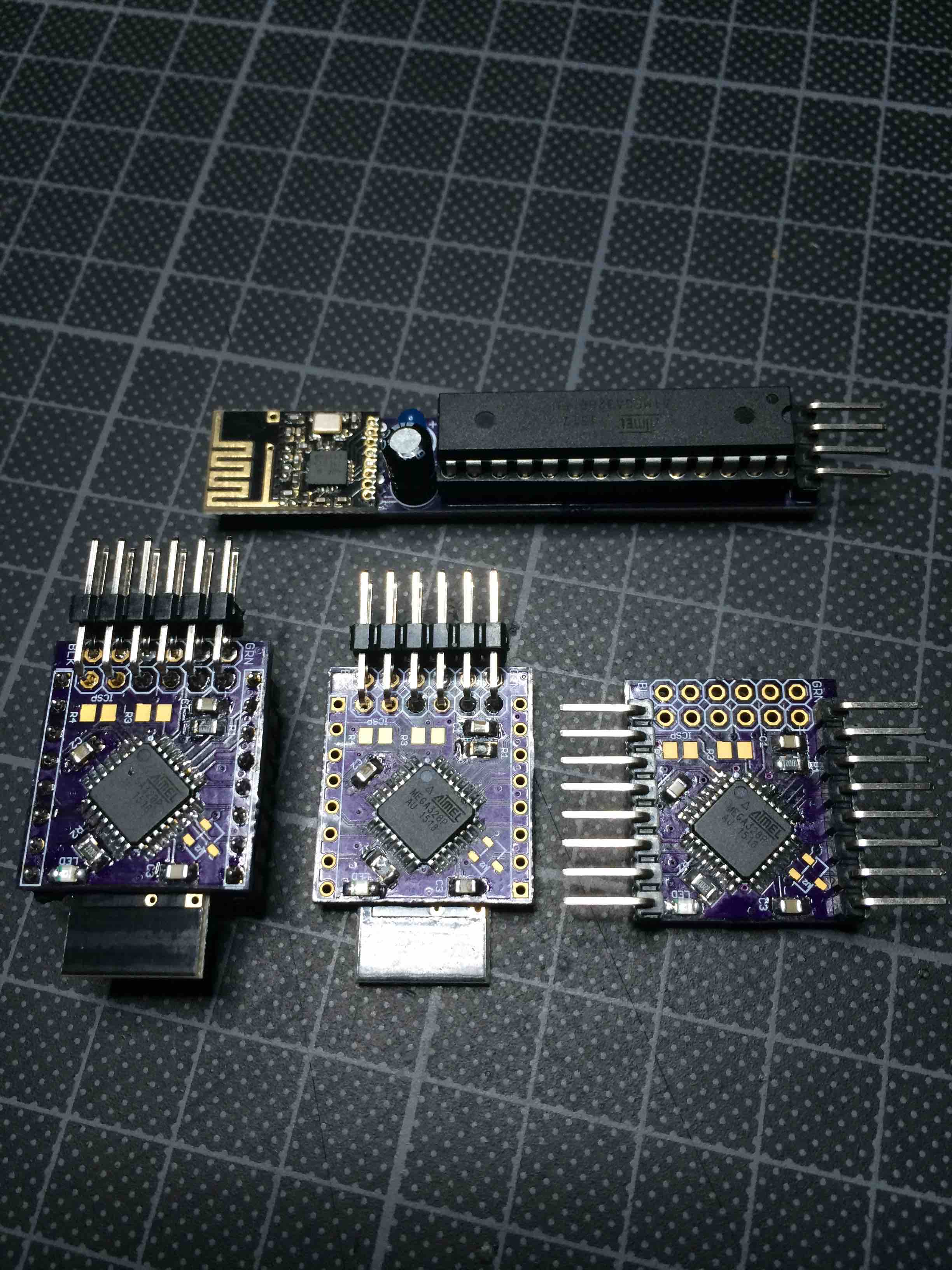
My first attempt at a full smd version of a minimal node. This one is just for testing the combination of an all smd node with a CR1620 battery.
Boards were made at OSH Park.
Node board:
https://oshpark.com/shared_projects/EO8F3MPe
Battery board:
https://oshpark.com/shared_projects/dZVILUiz
Still missing the 1M Ohm pull up resistors and the ATSHA204A (on order).
This node now runs as a switch detector node in my Domoticz network. The battery can handle the short bursts of transmission, but can not keep the LED on for more then a few seconds before you can see it dimming.
Mounting this node was as follows:
Start with soldering the MCU, the resistors and capacitors, then add the ISP and FTDI header. Program the mcu with the boot loader. Then check with a blink sketch if FTDI also works. After that, solder the NRF24L01+ on the bottom.
On each side there are 8 pins which each time include a VCC and a GND pin.
If the dual row header is like in the family picture below (furthest away from you), then the left hand side pin row (starting from furthest away towards you) has following signals:
GND - D2 - D3 - D4 - D5 - D6 - D7 - VCC
The right hand side has following pins:
VCC - A5 - A4 - A3 - A2 - A1 - A0 - GND
This means there are also I2C pins available:
A5 is also SCL A4 is also SDA
Power consumption without ATSHA204A and using internal Pull Up on D2 is measured as follows:
In deep sleep: 1.61 uA Sleep with Watchdog Timer running: 5.33 uA
Sending of voltage and pin status uses around 19mA for a short while (could not yet measure that timing).
Battery capacity is around 130 mAh. With an average consumption of around 10uA, this node should reach 380 days. If that would be true, I would be happy. In any case a year seems possible so I will set this node in a corner and let it signal it's battery voltage every hour. It's a dumb minion anyway, so it should be happy with any task :-).
My little stamps with their narrow brother all boot loaded and ready for duties:
