You can use a servo to control blinds or even the volume of an old stereo that is missing a remote.
Servos require a lot of power so you must power them separately (i.e. not from the Arduino).
You might need to fine tune the SERVO_MIN and SERVO_MAX parameters in the sketch to match your servo's range of motion. The example sketch supports servo's with a 180 degree range of motion.
Wiring Things Up
Start by connecting the radio module.
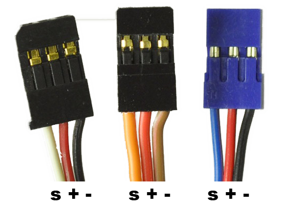 The servo cable colors can vary by manufacturer and mode so you should use the lead markings as illustrated above.
brown or black = ground (GND, battery negative terminal) red = servo power (Vservo, battery positive terminal) orange, yellow, white, or blue = servo control signal line
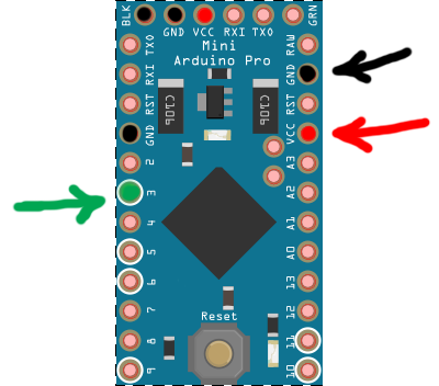
| Servo | Arduino | Comment |
|---|---|---|
| - | GND | Marked black |
| + | +5V | Marked red / Power source |
| S | Digital pin 3 | Marked green |
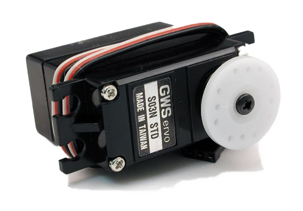
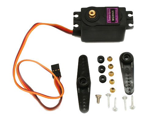
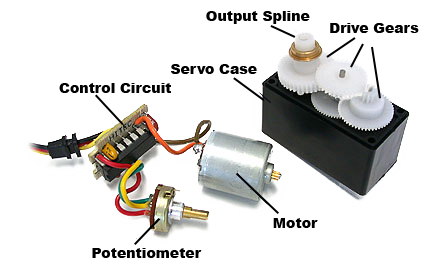
Inside and Parts
Example

/**
 * The MySensors Arduino library handles the wireless radio link and protocol
 * between your home built sensors/actuators and HA controller of choice.
 * The sensors forms a self healing radio network with optional repeaters. Each
 * repeater and gateway builds a routing tables in EEPROM which keeps track of the
 * network topology allowing messages to be routed to nodes.
 *
 * Created by Henrik Ekblad <[email protected]>
 * Copyright (C) 2013-2015 Sensnology AB
 * Full contributor list: https://github.com/mysensors/Arduino/graphs/contributors
 *
 * Documentation: http://www.mysensors.org
 * Support Forum: http://forum.mysensors.org
 *
 * This program is free software; you can redistribute it and/or
 * modify it under the terms of the GNU General Public License
 * version 2 as published by the Free Software Foundation.
 *
 *******************************
 *
 * REVISION HISTORY
 * Version 1.0 - Henrik Ekblad
 * Contribution by: Derek Macias
 *
 * DESCRIPTION
 * Example showing how to create an atuator for a servo.
 * Connect red to +5V, Black or brown to GND and the last cable to Digital pin 3.
 * The servo consumes much power and should probably have its own powersource.'
 * The arduino might spontanally restart if too much power is used (happend
 * to me when servo tried to pass the extreme positions = full load).
 * http://www.mysensors.org/build/servo
 */

// Enable debug prints to serial monitor
#define MY_DEBUG

// Enable and select radio type attached
#define MY_RADIO_RF24
//#define MY_RADIO_RFM69

#include <MySensors.h>
#include <Servo.h>

#define SERVO_DIGITAL_OUT_PIN 3
#define SERVO_MIN 0 // Fine tune your servos min. 0-180
#define SERVO_MAX 180  // Fine tune your servos max. 0-180
#define DETACH_DELAY 900 // Tune this to let your movement finish before detaching the servo
#define CHILD_ID 10   // Id of the sensor child

MyMessage msg(CHILD_ID, V_DIMMER);
Servo myservo;  // create servo object to control a servo
                // a maximum of eight servo objects can be created Sensor gw(9,10);
unsigned long timeOfLastChange = 0;
bool attachedServo = false;

void setup()
{
  // Request last servo state at startup
  request(CHILD_ID, V_DIMMER);
}

void presentation()  {
  // Send the sketch version information to the gateway and Controller
  sendSketchInfo("Servo", "1.0");

  // Register all sensors to gw (they will be created as child devices)
  present(CHILD_ID, S_COVER);
}

void loop()
{
  if (attachedServo && millis() - timeOfLastChange > DETACH_DELAY) {
     myservo.detach();
     attachedServo = false;
  }
}

void receive(const MyMessage &message) {
  myservo.attach(SERVO_DIGITAL_OUT_PIN);
  attachedServo = true;
  if (message.type==V_DIMMER) { // This could be M_ACK_VARIABLE or M_SET_VARIABLE
     int val = message.getInt();
     myservo.write(SERVO_MAX + (SERVO_MIN-SERVO_MAX)/100 * val); // sets the servo position 0-180
     // Write some debug info
     Serial.print("Servo changed. new state: ");
     Serial.println(val);
   } else if (message.type==V_UP) {
     Serial.println("Servo UP command");
     myservo.write(SERVO_MIN);
     send(msg.set(100));
   } else if (message.type==V_DOWN) {
     Serial.println("Servo DOWN command");
     myservo.write(SERVO_MAX);
     send(msg.set(0));
   } else if (message.type==V_STOP) {
     Serial.println("Servo STOP command");
     myservo.detach();
     attachedServo = false;

   }
   timeOfLastChange = millis();
}