
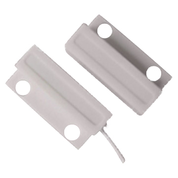
This is a simple but very useful example sketch for sensing binary things; like open/closed doors or the state of a wall switch.
The Arduino Pro Mini board has 13 independent digital input pins that can be used to sense the open/closed state of something.
By enabling the internal pull-up resistor (like we've done in this example) you don't need an external pull-up resistor. Just connect the push-button or reed switch between GND and one of the 13 independent digital inputs.
The sketch also takes advantage of the Debounce-library to filter out false triggers.
Wiring Things Up
Start by connecting the radio module.

| Sensor | Arduino | Comment |
|---|---|---|
| Switch | GND | Black |
| Switch | Digital pin 3 | Green |
Example
This example uses the external Bounce2 library found here. Please install it and restart the Arduino IDE before trying to compile.

/**
 * The MySensors Arduino library handles the wireless radio link and protocol
 * between your home built sensors/actuators and HA controller of choice.
 * The sensors forms a self healing radio network with optional repeaters. Each
 * repeater and gateway builds a routing tables in EEPROM which keeps track of the
 * network topology allowing messages to be routed to nodes.
 *
 * Created by Henrik Ekblad <[email protected]>
 * Copyright (C) 2013-2015 Sensnology AB
 * Full contributor list: https://github.com/mysensors/Arduino/graphs/contributors
 *
 * Documentation: http://www.mysensors.org
 * Support Forum: http://forum.mysensors.org
 *
 * This program is free software; you can redistribute it and/or
 * modify it under the terms of the GNU General Public License
 * version 2 as published by the Free Software Foundation.
 *
 *******************************
 *
 * DESCRIPTION
 *
 * Simple binary switch example
 * Connect button or door/window reed switch between
 * digitial I/O pin 3 (BUTTON_PIN below) and GND.
 * http://www.mysensors.org/build/binary
 */


// Enable debug prints to serial monitor
#define MY_DEBUG

// Enable and select radio type attached
#define MY_RADIO_RF24
//#define MY_RADIO_RFM69

#include <MySensors.h>
#include <Bounce2.h>

#define CHILD_ID 3
#define BUTTON_PIN  3  // Arduino Digital I/O pin for button/reed switch

Bounce debouncer = Bounce();
int oldValue=-1;

// Change to V_LIGHT if you use S_LIGHT in presentation below
MyMessage msg(CHILD_ID,V_TRIPPED);

void setup()
{
  // Setup the button
  pinMode(BUTTON_PIN,INPUT);
  // Activate internal pull-up
  digitalWrite(BUTTON_PIN,HIGH);

  // After setting up the button, setup debouncer
  debouncer.attach(BUTTON_PIN);
  debouncer.interval(5);

}

void presentation() {
  // Register binary input sensor to gw (they will be created as child devices)
  // You can use S_DOOR, S_MOTION or S_LIGHT here depending on your usage.
  // If S_LIGHT is used, remember to update variable type you send in. See "msg" above.
  present(CHILD_ID, S_DOOR);
}


//  Check if digital input has changed and send in new value
void loop()
{
  debouncer.update();
  // Get the update value
  int value = debouncer.read();

  if (value != oldValue) {
     // Send in the new value
     send(msg.set(value==HIGH ? 1 : 0));
     oldValue = value;
  }
}